This page is now historical information on the rev B development. See this page for current information
REV B Board testing discoveries
Boot failure
I had this on the revision A board and though it was fixed but it has appeared again. The symptom is at power on or a reboot you end up with only the power light on. I was able to reproduce it with my board not installed. It appears this is an occasional problem with the BBB and likely what I was seeing with the REV A board also. This is one persons solution. I found other similar descriptions. I didn't find a solution that was correct for my board running Debian. Below is what I did.
Backup your BeagleBone before performing these steps since it they go wrong you will have to reflash your board to recover. I hope to create a flasher image you can use that will put everything on you need.
Logged into the BeagleBone as root
git clone git://git.denx.de/u-boot.git
cd u-boot/
git checkout v2015.07 -b tmp
wget -c https://rcn-ee.com/repos/git/u-boot-patches/v2015.07/0001-am335x_evm-uEnv.txt-bootz-n-fixes.patch
patch -p1 < 0001-am335x_evm-uEnv.txt-bootz-n-fixes.patch
Edited include/configs/am335x_evm.h and added after
 #define CONFIG_SYS_I2C_MULTI_EEPROMS
the lines
 #define CONFIG_AUTOBOOT_KEYED           1
 #define CONFIG_AUTOBOOT_STOP_STR        "s"

make distclean
make am335x_evm_defconfig
make
If you have MLO and u-boot-img in /boot/uboot then
   cp MLO /boot/uboot
   cp u-boot.img /boot/uboot
otherwise
   dd if=MLO of=/dev/mmcblk0 count=1 seek=1 bs=128k
   dd if=u-boot.img of=/dev/mmcblk0 count=2 seek=1 bs=384k
reboot
3.3V Stability and loading
I saw some oscillation on the 3.3V from the BBB at particular loading. I have added a bulk decoupling capacitor to the production boards which stabilized it. Only one BBB of the 3 boards I tested showed this issued. In investigating this I found the BBB System Reference Manual (SRM) is deceptive on how much 3.3V power is available. In section 8.6.1 it says that 500 mA is available which I was assuming was accurate. In other sections it states that the power is provided by a TL5209A which is a 500 mA regulator. The problem is that LDO also powers chips on the BBB so 500 mA is not available. The SRM does not state how much power is used. Looking at schematics and datasheets my estimate is:
EMMC Flash     80 mA.
Ethernet PHY   54mA
MicroSD        < 100 mA for most chips
This leaves   266 mA

Estimate for my board is 230 mA.
Power usage should be OK but not the margin I thought I had. If you don't use both MicroSD and Ethernet the margin is fine. Using the USB port for extra storage doesn't use 3.3V and frequently is faster.
If you use the expansion connector you must limit load on 3.3V. Plenty of 5V is available which you can use a regulator enabled by the BBB 3.3V to generate a local 3.3V if needed.
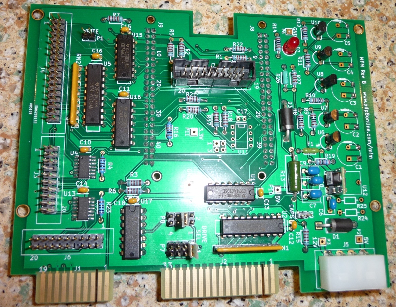
Below is the board assembled. I was asked if I could use the shrouded connectors that I had on the BOM instead. I checked with a sample of the people requesting assembled boards and all preferred them so the assembled boards will have shrouded headers for all connectors similar to the black ones shown. They will be blue since I think that part had a better plating.
I will be putting up updated assembly information shortly. The production order will have hard gold edge fingers which will withstand more matings and chamfered edge to allow easier mating of connector. Email me at address at bottom of page if you are interested.
The top page for mfm emulator information is here.
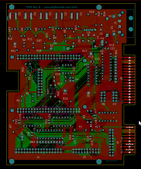
The layout for the next order of boards are here Under each version the pdf directory has the schematic (top.pdf) and plots of the board layers. The bom directory has the bill of material. The board is released under the Creative Commons Attribution-ShareAlike 4.0 International Public License..
I have made the following changes. Changes that just fix errors listed listed here are not listed on this page.

Suggestion I have gotten or thought of for future builds: