Top level of build instructions
This page documents how to assemble the MFM reader/emulator PCB. See here for SA1000 adapter assembly. Current board is Rev D. Mouser/Digikey BOMS below have been updated to rev D. If you have a rev C board make the following changes:
If you have any questions, improvements, or corrections email me at the address at the bottom of the page.
I have tested the BeagleBone Green (BBG) and it works fine for the MFM emulator and is slightly cheaper. Only recent Beaglebone Blacks have the fix for Ethernet not always working on power on. All references to BeagleBone Black (BBB) in these pages also apply to BBG unless otherwise noted. The BBG wireless will not work.
The 10F capacitors are recommended. They have around 35 second run time which gives plenty of time for shutting down when using a reasonable size write buffer. The run times are not right for the rev B board but the rest of the discussion on write times and storage options is still useful.
If you are mounting the capacitors on the top AVX has 12.5x20mm caps SCCT20B106SRB/SCCT20B106PRB which should fit better. I have changed the Digikey/Mouser BOM to use these.
I recommend a shrouded connector for J7 to prevent installing the cable wrong. Plugging in backward connectors with power may cause damage.
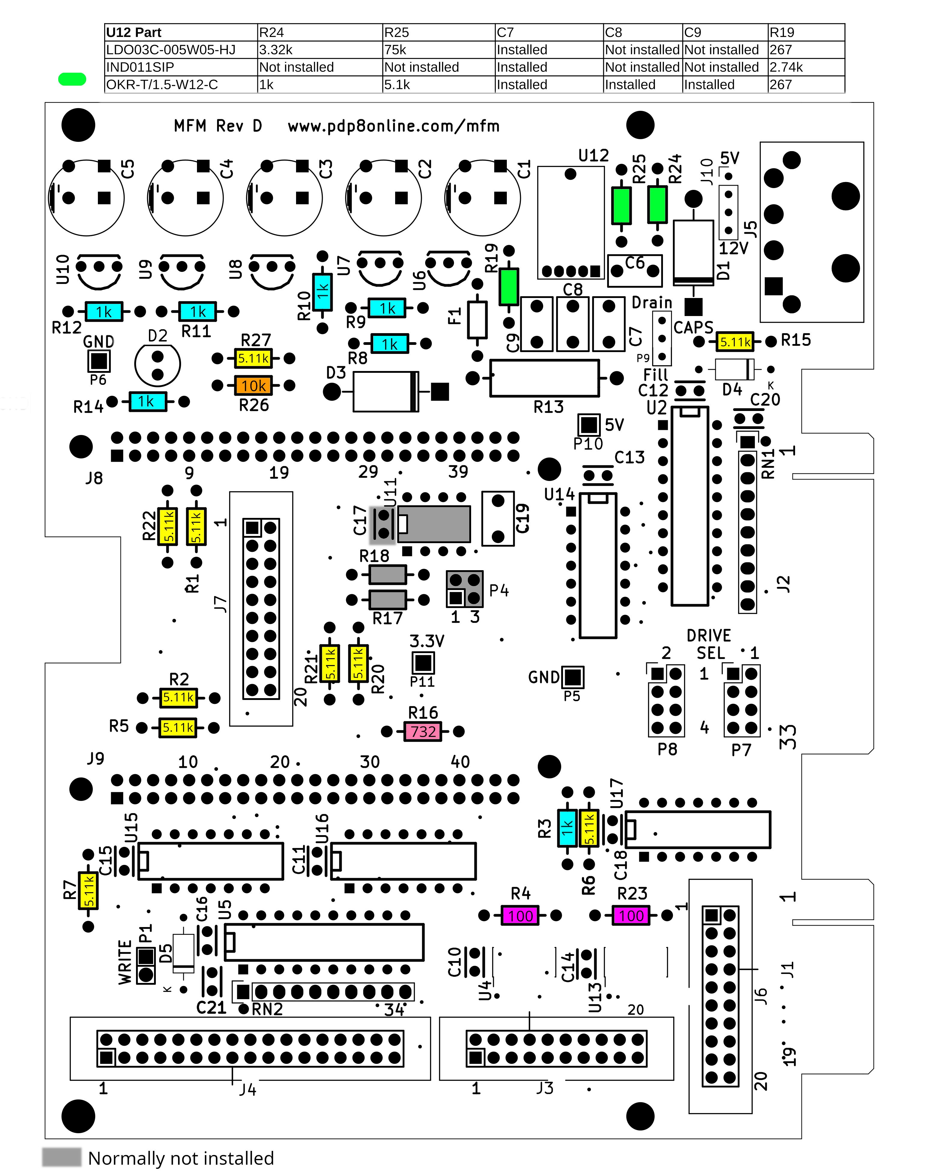
BOM update August 2023.The original OKR-T/1.5-W12-C part seems to be available again. Its somewhat cheaper if you want to switch to it but since it is going end of life I'm not changing the BOM to it. Make sure you use the correct R19, R24, and R25 and which of C7,C8, and C9 should be installed. See the table in the text BOM after the parts list if you switch part in the Digikey or Mouser BOM's.
Use the Bill of materials to order the components to build the board. I used Digikey and Mouser though other distributors are likely to have suitable parts. The Digikey and Mouser BOMs get updated most often. The spreadsheet/HTML BOM gets updated less frequently. The parts on the schematic are not updated with BOM changes.
Here is a Mouser BOM For building using the Mouser BOM you need to cut down the 50 pin strips to 46 for the Beaglebone. The extra pins are used for P1. If you don't want to have to use what you cut off you can order two 571-5-146269-1.
Here is a Digikey BOM.
It will come up with a screen showing a couple parts. These are parts that
are cheaper to order more of. Either click submit to take as is or click
the view options link (may need to scroll right to see) and select cheaper
quantity then add. I didn't want to change the BOM quantity in case you are
ordering multiple copies.
For Digikey the cheapest option was to buy two 72
pin strips to cut down to 46's for the Beaglebone J8,J9; 8 pin for P7,P8;
and 2 pin for P1. If you don't want to cut order two S2011E-23-ND, two
609-3203-ND, and two 5-146269-1-ND instead of two 609-3294-ND. I'm
not sure how with Digikey you order multiples of the BOM if you are building
multiple
boards. You may be able to create multiple carts then combine then.
You will need a micro SD card to reflash the beaglebone. If you don't have them around order one >= 2 GB.
TTI has the super-capacitors cheap. Also Newark
The distributor BOM's above include all parts except U11, P4, R17, R18, and C17 which you don't normally need. With the current Artesyn DC/DC C8 and C9 are also not needed so aren't included. They do not include parts for drive activity LED. See the bill of material for parts you may wish to add for drive activity LED or for cable to connect to J6 if you wish to emulate two drives and don't have a female-female 20 pin cable.
If you are using it for disk reading and not emulation and have not installed U12 and other power components you may wish to buy a 5V power supply that connects to the BBB barrel jack. The BBG does not have that jack so you will need to power through the MFM board connector.
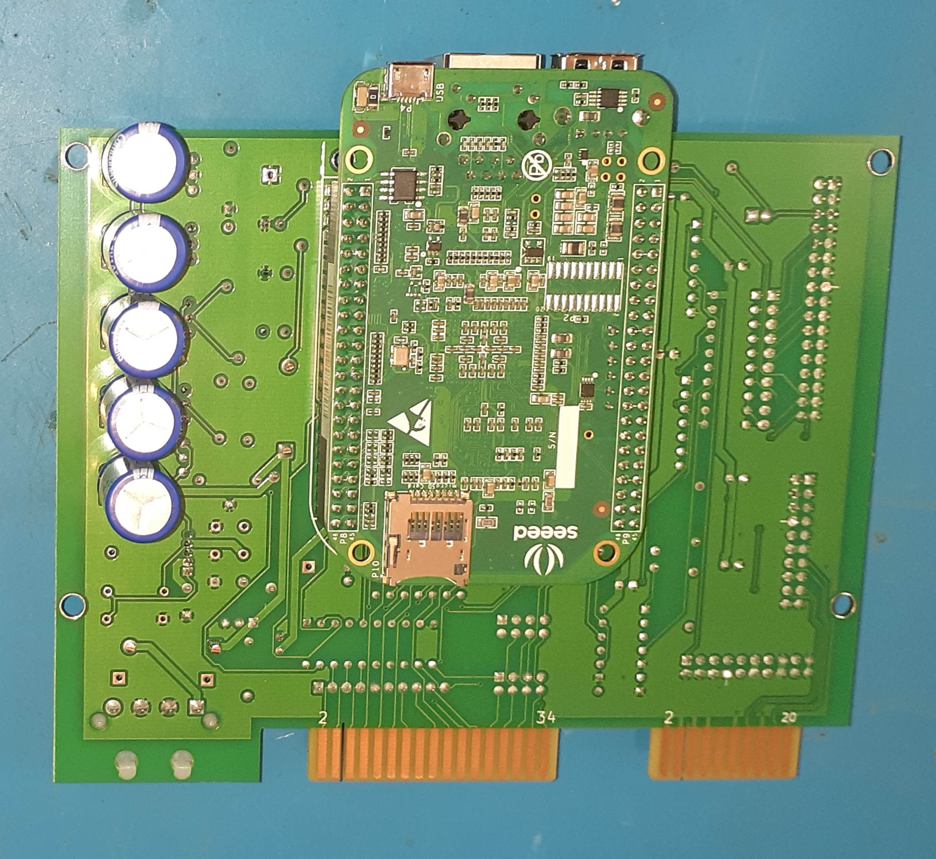
The J8/J9 connectors for the BBB (U1) should be installed on the back/solder side of the board with the short pins soldered to the board.
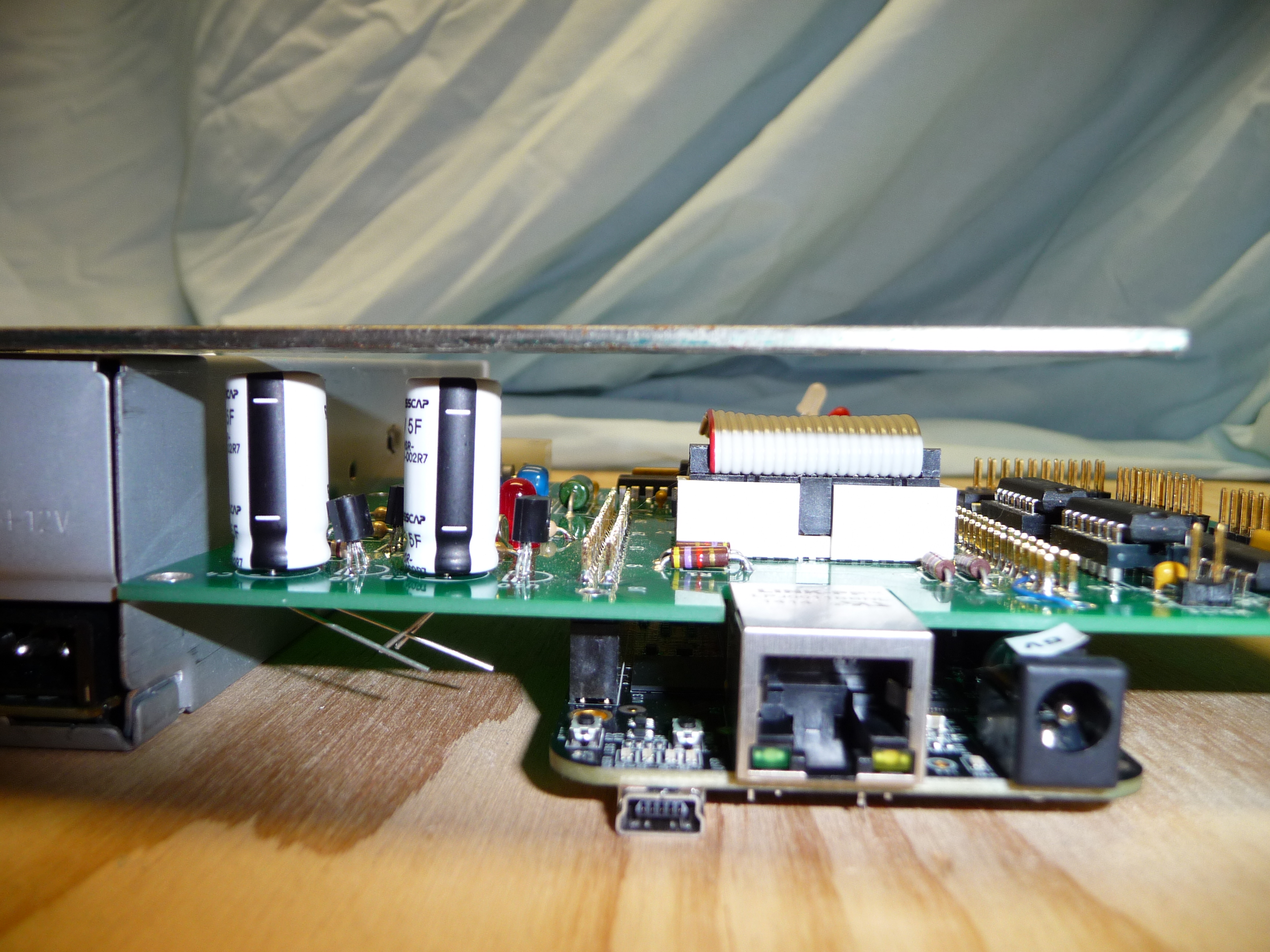
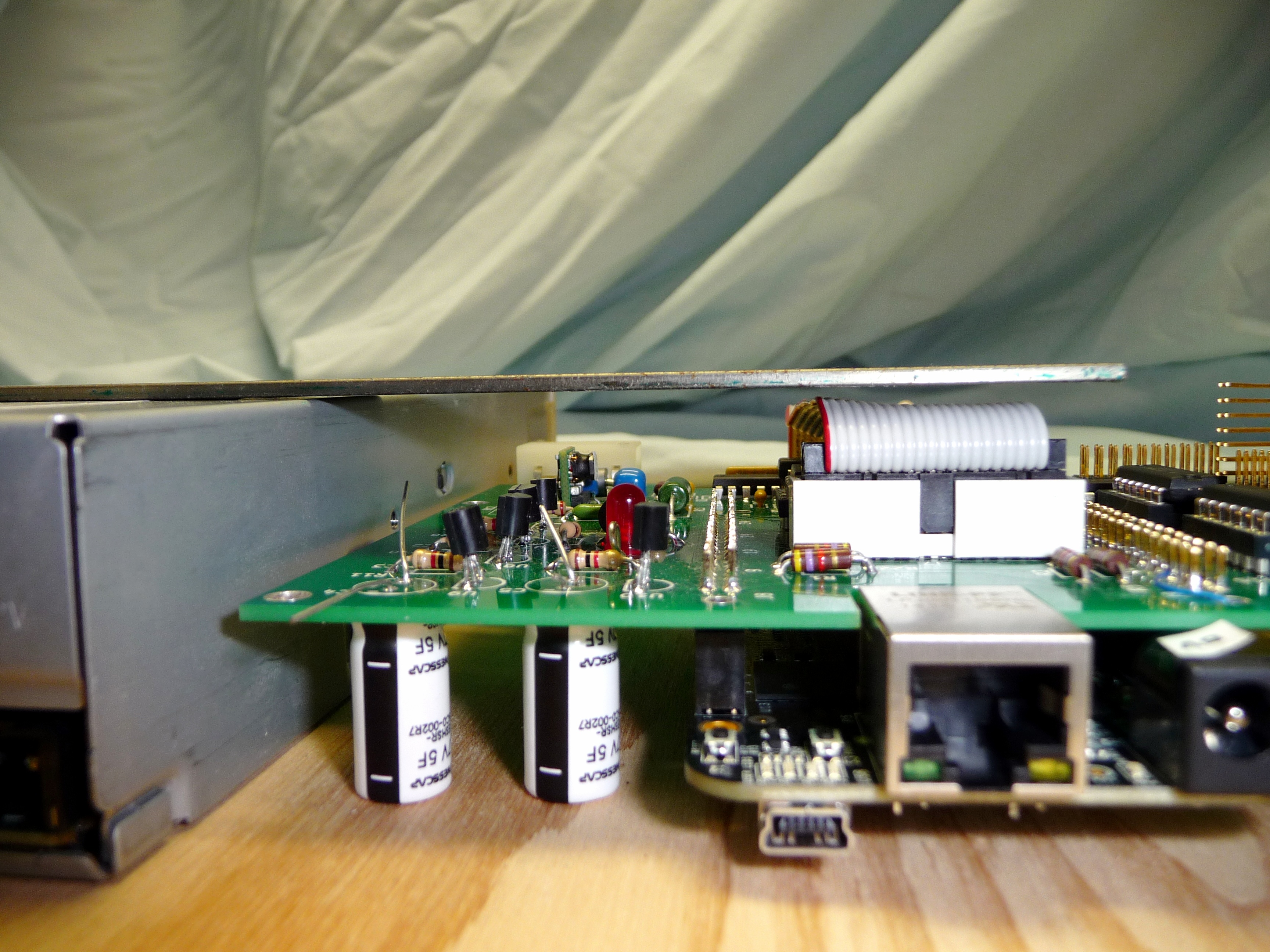
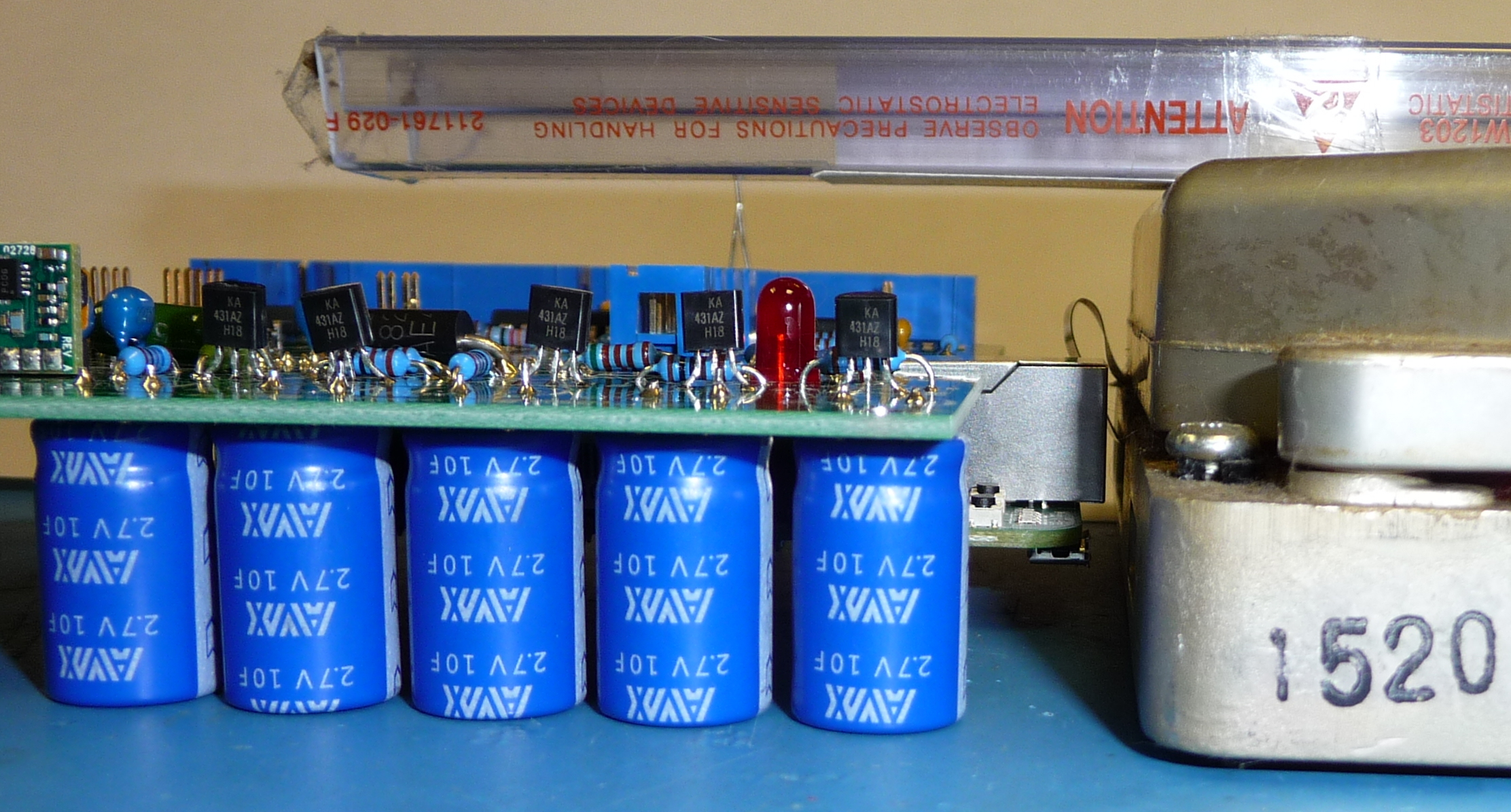
The capacitors C1-C5 may be installed on the side of the board that makes it fit better for the mounting method chosen. With the 5F caps on the top, the assembled height is only slightly smaller than a half height drive so the board mounting will need to be accurate to fit. With the capacitors vertical on the bottom the height is less which may make it easier to mount. The pictures show the Rev A board and the Rev B board with the short AVX 10F capacitors.
The 10F caps have plenty of space mounted on either side when installed in a full height drive bay.
If you wish to use 10F caps in a half height
drive bay they will either need to be the AVX SCCT20B106SRB installed
on the bottom or any cap installed laying down. The AVX capacitors are
the same height as the 5F shown above. The pads closest
to the edge of the board should be used when installing the tall capacitors
lying down.
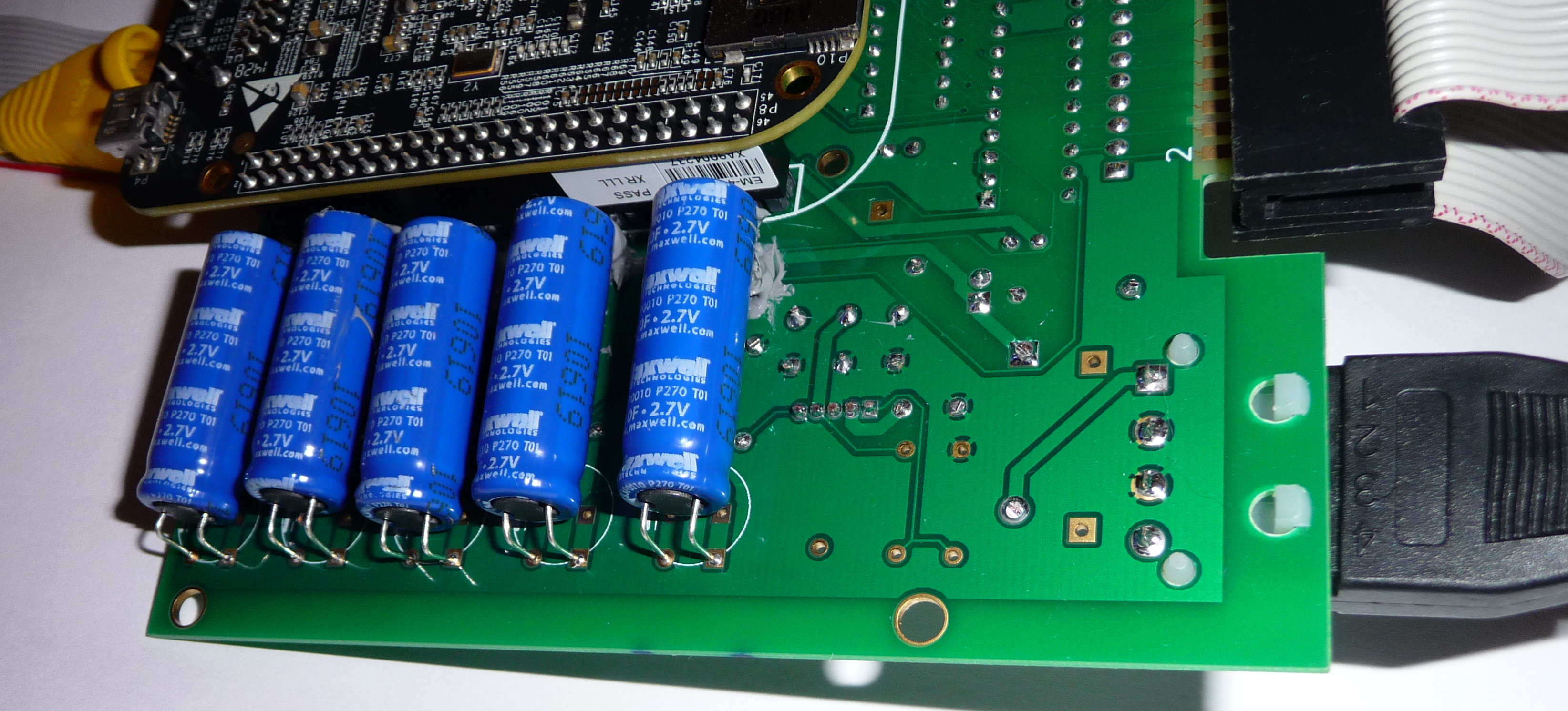
You will need to bend the leads to install the capacitors. I recommend
holding the
lead with needle nose pliers when bending to avoid stressing the capacitor
seal. I used RTV silicone to
attach the capacitors. Use non-acetic-acid cure RTV (that doesn't
smell like vinegar) to prevent corrosion. If you are buying from a distributor
it will be listed as suitable for electronics. The consumer GE silicone II
caulk is OK. You can arrange them to avoid some of the leads but not all.
If a lead pokes through the insulation on the capacitor bad things will
happen. To mount them I cut a thin cardboard spacer to hold the capacitors
off the leads. I put the RTV on the one end then installed the capacitors
over the cardboard spacer. I soldered the capacitors the next
day after the RTV was dried then removed the cardboard.
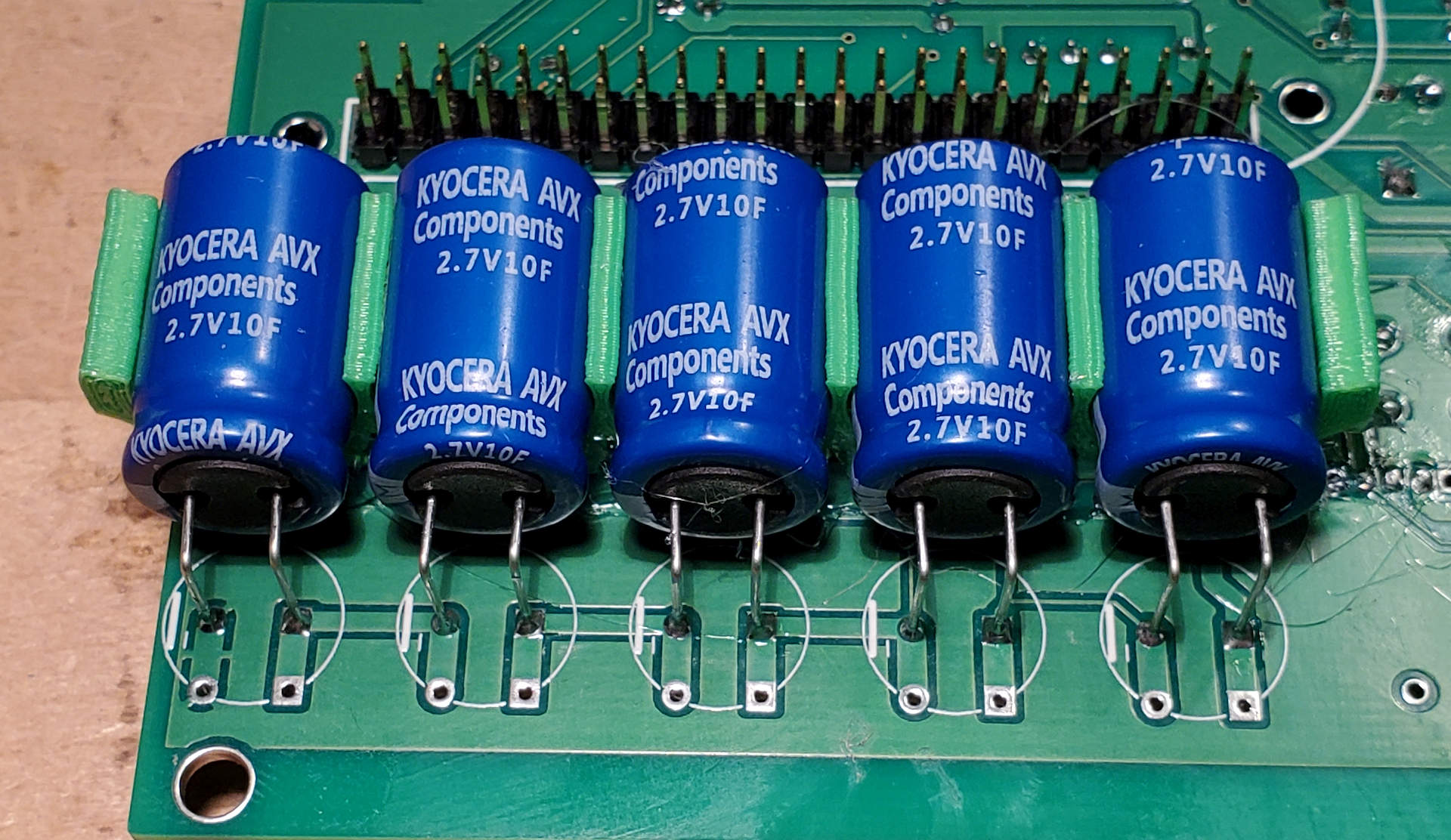
John Dammeyer created this 3D printed capacitor holder thats much nicer looking
that globs of RTV. He attached it with hot melt glue.
Installation instructions
CapacitorClip.pdf
CapacitorClip.stl
CapacitorClip.stp
The cables mating to J4 frequently have pin 15 plugged for polarization so you may wish to remove that pin before installing the connector. The pin is marked with a little line in the silkscreen.
The cables mating to J3 and J6 frequently have pin 8 plugged for polarization so you may wish to remove that pin before installing the connector. The pin is marked with a little line in the silkscreen.
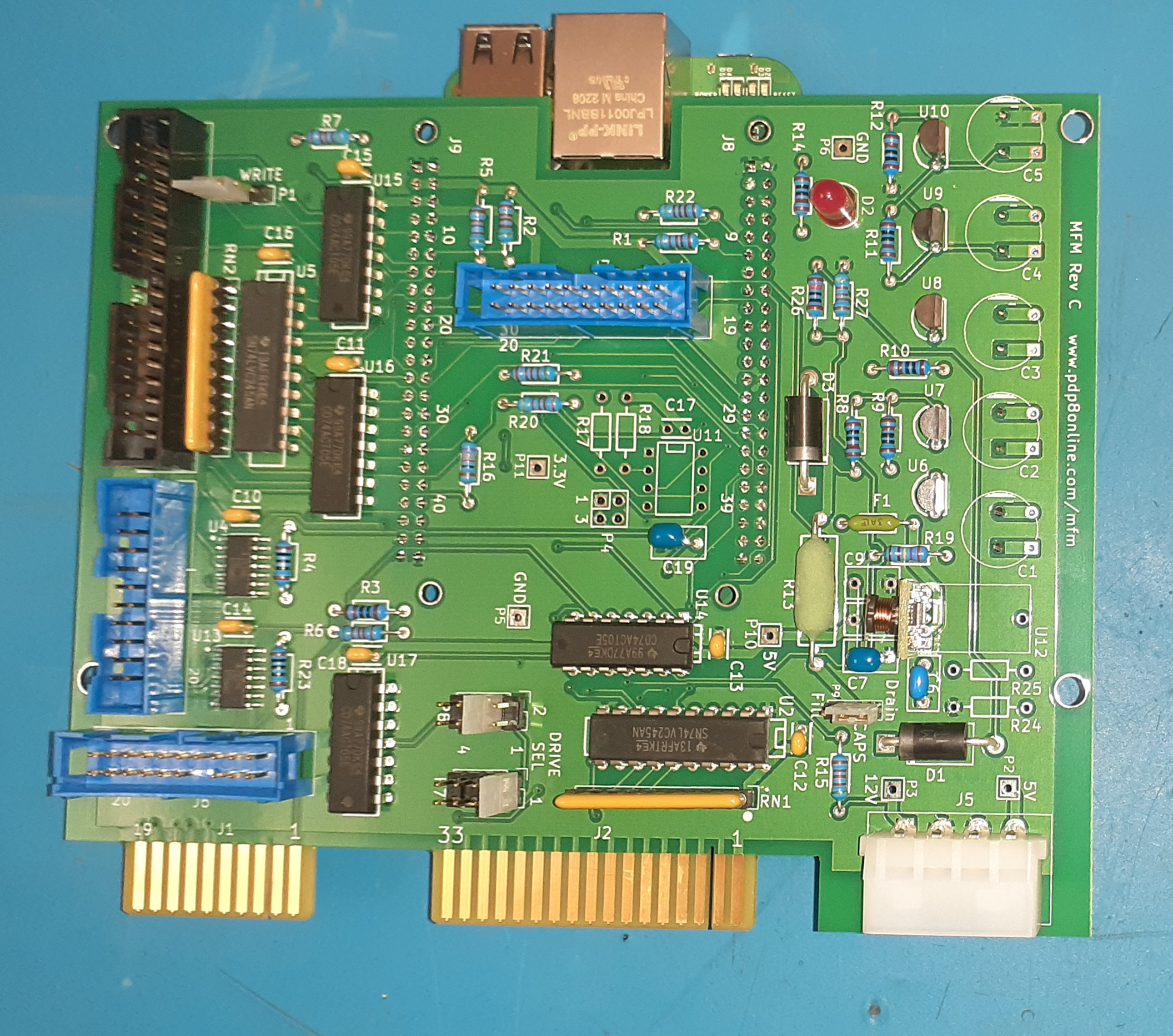
The primary part DC/DC converter U12 is not marked clearly with which pin is 1. See assembled picture at the top of page and below for correct orientation. Also due to the close lead spacing watch out for shorts when soldering.
I installed parts by height so when the board is flipped to solder they get pressed against the board. I started with the surface mount IC's. Next the 1/4 W resistors values with low quantity, then the 1k which are near the big capacitors and then the 5.11k in remaining spots. The holes are .4 inch spacing if you have a lead bender. If you spread the leads they won't fall out when you flip the board. I used this color coded chart to help me find the resistor locations. I install some components then solder before they start getting in the way of soldering then repeat. I install R13 a little off the board since it can get somewhat hot. A reasonable order for the rest is F1, .1 capacitors, IC's, XRN1,RN2, R13, other small capacitors, P1, P7-P9, J3, J4, J6, J7, J5, U6-U10, D1, D3, D2, U12, J8, J9, C1-C5. You should solder a corner pin on each end of J8 and J9 and verify they are mounted straight before soldering all the pins. You may use what works for you. Be careful of component orientation. Socket XRN1 suggested for RN1 so the terminating resistors can be removed if the emulator is used on the same cable as another drive that has terminating resistors installed. The RN resistors need to have the end marked with the dot at pin 1. The last drive on the cable is supposed to be terminated and others not terminated. J5 installs easily if you first put the plastic tabs through the board and push it forward so you can get the rear pins in.
After you are done inspect the board for shorts,
unsoldered leads, components installed with incorrect orientation, missing
components etc.
If you installed U12 power up the board without the BBB and verify the 5V is correct (measure P10 to P5). P9 jumper will need to be installed to enable the holdup capacitors. On the rev C board the jumper has two positions. On fill the capacitors will charge. On drain the capacitors will be discharged. I wait until the power light on the beaglebone goes off before moving the jumper to drain. For either board if the jumper is off the capacitors won't charge. It's probably a good idea to test the capacitors before hooking up the BBB. After powering the board verify the capacitors have similar voltages which should be around 2.3V across each of C1-C5. DON'T INSTALL the BBB while voltage is still on P10 (5V). This may damage your BBB. If the LED is not lit it is safe to install the BBB. It may take an hour for the bleed resistor to discharge the capacitors after they are powered up. For rev C set the jumper to drain to quickly discharge the capacitors. For rev B you can speed this up by connecting a bleed resistor from R13 to GND. 560 ohms keeps peak dissipation to 1/4 watt. It will get hot enough that you don't want to touch it. R13 can also get warm on power up. I haven't yet found out what a backwards capacitor will do. Install the BBB ensuring proper alignment of the connectors.
When not installed in a computer removal of P9 jumper will disable the holdup capacitors so you don't have to worry about the stored energy when moving or storing the board.
For software installation and further testing see
Top level of instructions
The board has capacitors to provide power for a short time when power is lost to perform a clean shutdown of the operating system. This prevents corruption of the flash memory or data loss. If this is not desired don't install the following components: C1-C9, U6-U10, R8-R16, R19, R24, R25, D1-D3, F1, and U12. Connect P2 (5V) to P10 (5V) unless you are using the BBB barrel jack to power the board.
A possible option instead of the capacitors is a battery on the BBB. I haven't tried or evaluated this solution so you will need to evaluate the suitability. It requires modification of the BBB.
If the ability to read an existing disk is not desired don't install components C11, C16, J3, J4, P1, U5, U16, R5, and R7. If both reading a second disk and emulating a second drive is not desired don't install components U15 and C15.
If drive emulation is not desired don't install components U2, U14, RN1, XRN1, R3, C12, and C13.
If second drive emulation is not desired don't install C14, U13, J6, P8, R22, and R23.
If BBB shield auto identification of pins used is not desired don't install U11, P4, R17, R18, and C17. R20 and R21 can also not be installed if I2C is not used on J7. Programming the EEPROM is at least as difficult as setting up a script to perform the configuration at boot so it's probably not worth installing these components.
LED D2 is used to warn that the capacitors are still charged. If this is not needed don't install D2 and R14.
If expansion signal connector is not desired don't install J7. If all you want is drive LED's you can not install J7 and solder wires for them where J7 is installed.
Parts were chosen to be available at Digikey and Mouser. If a part was available from both it was chosen otherwise an alternate part is shown in the parts list. You may be able to substitute parts with the particular distributor you are using to get a lower price.
For the headers both shrouded and unshrouded headers are listed. Use the type you like. The gold plating thickness varies on the parts listed. Minimum is 10 micro-inch (uin) gold or 30 uin GXT gold. If thicker plating is desired to allow many unmating cycles other parts may be chosen.
For DC/DC converter U12 the primary part requires the external capacitors C6-C9. The datasheet for the secondary part LDO03C says it does not require external capacitors though does recommend a 1 uF input capacitor. The capacitors on the parts list can be installed for better filtering. Other options would be one of the 10 uF for the input and output or just put the .1's in for C6-C9. With this board version the secondary part is not recommended.
I have purchased many of the parts to verify the parts list is correct but not all. You may wish to check headers and alternate parts before purchasing.
The board may be powered through the drive power connector J5 or the BBB barrel power jack depending on how the board was assembled. It can't be powered by the USB connector.
The board has a bank of super capacitors to provide enough power to allow the software to cleanly shut down the BBB operating system when power is lost to prevent file system corruption and data loss. The board input is 12V with a DC/DC converter to generate 5V. If the backup power is not desired a pad is provided to allow the input 5V to power the board instead of the DC/DC converter.
The capacitors are rated at 2.7V maximum. With 5 in series the theoretical rating is 13.5V. Due to mismatch in capacitance when charging the voltage will not divide evenly between the capacitors. U6-U10 clamp the voltage on each capacitor to 2.5V. With .3 volt drop across D1 the 12V input should be below 12.8 volts to prevent the entire string of regulators trying to clamp the input voltage. Resistors R8-R12 prevent the mismatch in capacitor leakage current from unbalancing the voltage on the capacitors.
R13 sets the peak charging current and limits current through voltage clamps on capacitors. The 10 ohm resistor sets peak current to about 1.2A. The value was picked such that if the capacitance of one capacitor is 20% greater than others, it will keep the current through the voltage regulator under the maximum rated current. Adjust the value if a different peak charging current is desired. Make sure the part chosen can withstand the peak power dissipated. With this resistor it will take about 70 seconds to charge the capacitors to 90% of final voltage.
Super capacitors were chosen since they are expected to be much more reliable than batteries though it does increase the cost. As an alternative some people have attached a battery to their BBB. I have not tried the battery method of powering the board or evaluated how they are attaching the battery.
J7 is provided to allow switches for controlling operation or displays for status. See J7 Expansion connector for drive select LED implementation. Other usage needs to be implemented by user. For my usage I only desire to select between a few images. I am planning to hook up a rotary switch that I can use to select the image at boot time. I was also going to see if a wireless USB adapter gets enough signal inside the chassis. This will allow me to back up the emulation image and any other playing I wish. The USB connector ended up in a bad location so a short extension cable may be needed to get the USB WIFI closer to an opening for better reception. The BBG USB connector is in a better location.
The HDMI video output is not usable with the MFM emulator board.
All signals must be 3.3V. 5V and 3.3V power is provided. Also note that expansion 10, 11, and 12 are on pins used to select boot device. These pins have 100k resistors to +3.3 or ground. Anything connected to them must ensure they still have valid logic level at power up either by limiting loading or with a lower value resistor. See the BBB system reference manual for interfacing information.
The write jumper P1 when removed ensures software errors can't cause writing to a drive being read. R7 prevents the write line from being seen as a low if the termination is not installed on the drive if this board is powered from the same supply powering the drive. Its value is high enough that it will not load down the write signal if this board is powered off while the drive still has power.
The EEPROM for shield configuration was designed in the board. Shields that are sold pre-assembled are supposed to have the EEPROM. It's not really useful for kit boards.