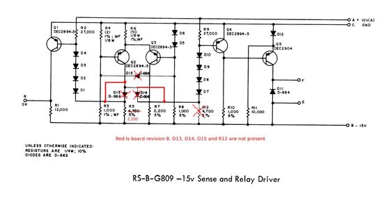

This shows the schematic of the G809 in the maintenance manual marked up to match the revision B board in my machine. The board I have must be an older revision since it has a design error. The Q1, D1-D4 and Q4, D7-D10 are both connected to R5. When Q2 turns off it is supposed to turn on Q1 and Q4. Due to mismatch of the forward voltages of the two strings Q1 turns on fully and Q4 only partially turns on. This caused the relay on the memory outputs to chatter or not turn off when it should. This may be why the relay contact was damaged since each turn off was equivalent to turning the machine on and off many times. It would be difficult to modify the board to the later revision. I made a simpler change of adding a 220 ohm resistor in the D1-D4 chain which is shown in the next picture. While resolving this problem I found out the hard way that the DEC2894 transistors have a 12V breakdown voltage so without the clamp on the G808 board connected Q1 will fail due to the -15V collector pulldown.
Back to Previous page All of PDP-8 (Straight 8) Power Supply pictures