|

|
I made this board for my Straight 8 computer to fix switch bounce causing the front panel to operate improperly. The one with the edge connector goes inline with card in PA5. The wires to the W026 board can make it difficult to plug in. The other card goes in an open slot to provide power. I misjudged J2 height so mated connector wouldn't fit in slot so soldered wire directly to board. For the power pickup I put it PC4 with no board next to it. The two boards are identical just populated differently. There are some resistors that probably aren't needed. I only noticed the W026 boards had resistors on them after I had finished the board layout. Load address, deposit, examine, and continue DEC used -15 and ground connected to the two poles of the switches so those are well debounced. For some reason start and stop are done as single pole grounding the signal.
The front panel now works much better. I was able to toggle in a 21 instruction program without it messing up. Before it would have messed up a couple times.
For power board install J3 and R13. For debounce install everything other than J3 and R13.
I have some extra bare boards if you want them. The small components are a pain to solder.
Kicad project. PDF schematic. BOM such as it is.
Edge connector is made by ECS. Another discussion. They aren't readily available but some people have bought a bunch and are selling them.

|

|
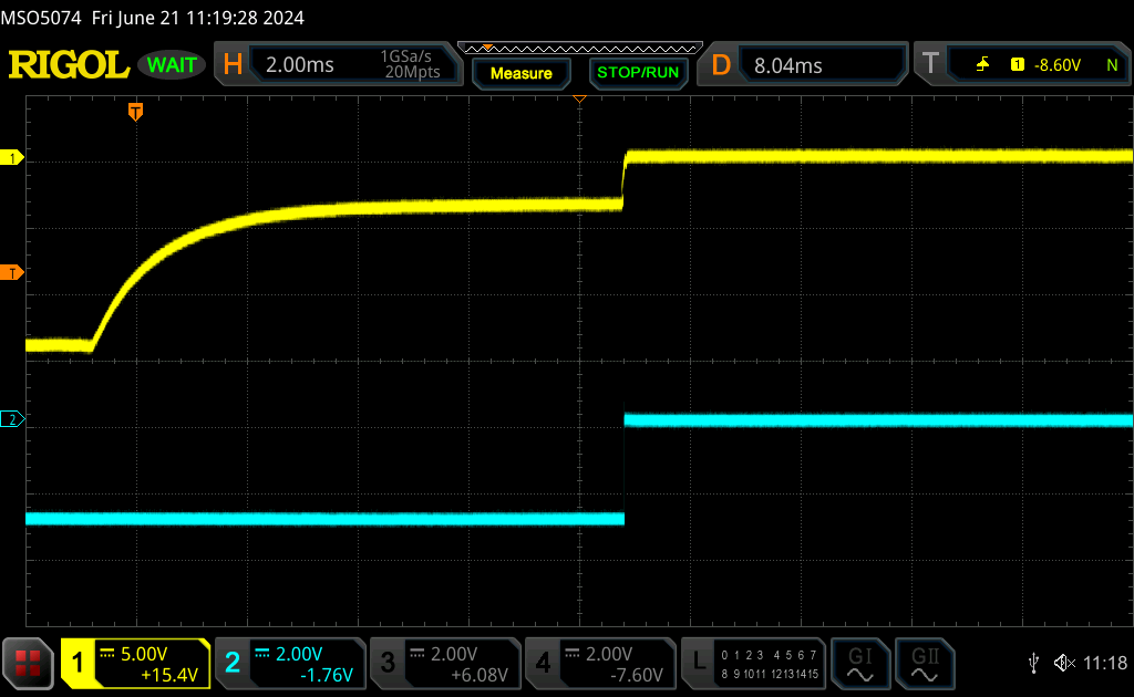
| Examine waveform. When -15 pole opens the IC clamp to ground (-3.3) pulls the signal up. When the ground pole closes it then quickly is pulled to ground. This is signal into debounce card and signal out of card. | |

|

|
Feel free to contact me, David Gesswein djg@pdp8online.com with any questions, comments on the web site, or if you have related equipment, documentation, software etc. you are willing to part with. I am interested in anything PDP-8 related, computers, peripherals used with them, DEC or third party, or documentation.
PDP-8 Home Page PDP-8 Site Map PDP-8 Site Search